
Battery control experts · Brno, CZ

We make batteries better.

Volteek designs modular battery control systems that measure every cell, balance charge and protect packs up to 1200 V. Built for motorsport, industrial machines, energy storage and space.

Max. operating voltage
1200V
Cells in series
380
Cell voltage accuracy
±1.9mV
Pack V & current refresh
2kHz
Standby power
<24mW
Why Volteek

Battery control solutions with end-to-end protection.

The system is modular, so additional modules integrate without redesign. Tailor it to your requirements, whether that is motorsport, energy storage or space.

Safety first

Every cell, sensor and switch is watched.

Protection is designed in at every level, with redundant paths for the measurements that matter most.

  • Intelligent safety circuit (iSDC)
  • Isolation resistance measurement
  • Contactor control and monitoring
  • Redundant communication and temperature measurement
  • Galvanically isolated communication
Advanced features

Know what the pack can do right now.

Accurate state estimation and stored history turn raw measurements into decisions for drivers, operators and fleet teams.

  • Accurate SoC, SoH and SoP
  • Predictive maintenance
  • Remote management
  • Up to 16 GB on-board storage
Scalable architecture

From one 8-cell module to 1200 V.

Chain cell modules as the pack grows. The same master, firmware and tools carry across every project.

  • Modular building blocks
  • Operating voltage up to 1200 V
  • Up to 380 cells in series
  • Wide cell chemistry support
BCS platform

Five modules. One battery control system.

Each module does one job well. Select a module in the diagram or the list for its key data, or open the products page for full specifications.

Battery pack · up to 380 cells in series ··· isoCAN daisy chain isoCAN BCS-AM01–04 Current BCS-PM01 Power To inverter / charger BCS-MM01 Master Algorithms · logging · comms BCS-DM01 Display Vehicle · EMS · charger CAN FD · Ethernet · RS 485 · GPIO
High-voltage path Isolated signal link Simplified topology

Intuitive design

Modules are detected and configured automatically, then tuned in a simple GUI.

State of the art

High-accuracy measurement with sampling up to 2 kHz.

OEM

System development and design, plus integration support for your product.

Active cell balancingIn development

Move energy between cells instead of burning it.

In a series pack the emptiest cell decides when the whole pack stops. Passive balancing bleeds the fuller cells down to match it and turns the difference into heat. Active balancing moves that charge to the cells that need it, so the pack keeps more usable energy.

Our cell module with active cell balancing is in development

Passive balancing

Bleeds to heat
0Cell spread
0Usable charge
0Lost as heat

Active balancing

Redistributes
0Cell spread
0Usable charge
0Lost as heat

Simplified illustration: 16 cells in series, state of charge per cell, active balancing modelled at the expected conversion efficiency of about 96%. The dashed yellow line marks the emptiest cell, which sets usable pack charge.

Longer battery lifeCells stay matched, so no single cell is pushed harder than the rest.
Higher reliabilityWeak cells are supported instead of becoming the failure point.
Better efficiencyAbout 96% of the energy moved stays in the pack instead of turning into heat.
More energy densityMore of the installed capacity is usable on every cycle.
Typical applications

Built for packs that work hard.

The same platform scales from a motorcycle to grid storage. These are the fields we design for most often.

Mobility

High current, high vibration and no room for surprises on track or on the road.

  • Fully electric and hybrid racecars
  • Electric motorcycles
  • Public transportation
  • Mining vehicles

Industry

Long shifts, harsh sites and machines that have to report their own health.

  • Construction equipment
  • Agricultural machinery
  • Warehouse automation
  • Industrial robots

Energy

Storage that runs for years, where every percent of capacity has a price.

  • Grid-connected storage
  • Backup power systems
  • Demand response systems
  • Remote off-grid power

Interested in working with us?

Tell us about your pack or project and we will get back to you.

Send us a message
Products

Battery control solutions.

Engineering the future of energy

Advanced high-voltage technology that improves reliability, energy density and lifespan. Built for high-reliability applications, with energy management you can customise for your industry.

Five modules are available today. A cell module with active cell balancing is in development.

Max. operating voltage
1200V
Cells in series
380
Cells per cell module
16
Standby power
<24mW
System overview

A self-powered system for efficient energy control.

An integrated high-voltage DC/DC converter powers the system straight from the pack. It supports up to 380 cells in series, with up to 16 cells per cell module, and combines precise measurement with advanced state-of-charge algorithms. Galvanically isolated communication, fault detection and the Intelligent ShutDown Circuit (iSDC) keep the pack safe, while 100 Mbit/s Ethernet, CAN 2.0B, USB, RS 485 and GPIO connect it to almost any application.

Self-powered system

  • Integrated HV DC/DC converter
  • Ultra-low power mode

High-voltage architecture

  • Operating voltage up to 1200 V
  • Up to 16 cells per cell module
  • Up to 380 cells in series
  • Galvanically isolated communication

High-accuracy measurement

  • Cell voltage accuracy down to ±1.9 mV
  • Pack current accuracy ±0.01 A
  • Pack voltage accuracy ±0.1 V
  • Advanced SoX algorithms

Broad connectivity

  • Internal redundant isoCAN bus
  • 100 Mbit/s Ethernet
  • Dual CAN 2.0B bus
  • USB, RS 485
  • GPIO

Fault detection

  • Cell voltage refresh rate up to 900 Hz
  • Up to 6 + 6 + 2 temperature sensors per cell module
  • Redundant communication and temperature measurement
  • Intelligent ShutDown Circuit (iSDC)

Customisation

  • Configurable hardware for your application (cell sensing adapters, display size and resolution…)
  • Custom firmware and software features on request
  • Engineering support for tailored solutions
  • Firmware update over CAN

Need a tailored configuration?

Hardware, firmware and software can be configured to suit your application.

Request a quote
BCS-MM01

Master Module

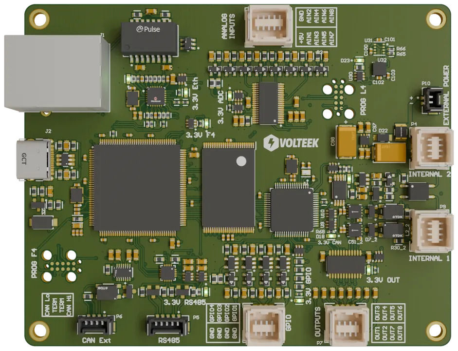
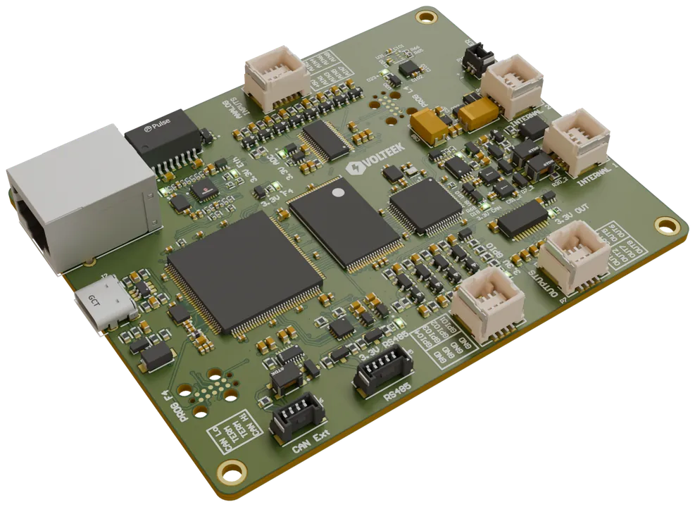
Handles communication with the user and with peripheral devices such as the cell modules, power module and charger. Two processors increase cybersecurity and reduce power consumption.

Parameters

Power consumption
< 2.5 W
Standby power
< 200 µW
Processor
Dual-processor architecture
State estimation
Advanced SoX estimation
Storage
Up to 16 GB internal
Outputs / inputs
8 low-side outputs (1 A sink), 4 inputs
Communication
CAN FD / CAN 2.0B, 100 Mbit/s Ethernet, RS 485, GPIO

Order info

Part numberModule
BCS-MM01Master Module
Ask about BCS-MM01

Or email info@volteek.com

BCS-PM01

Power Module

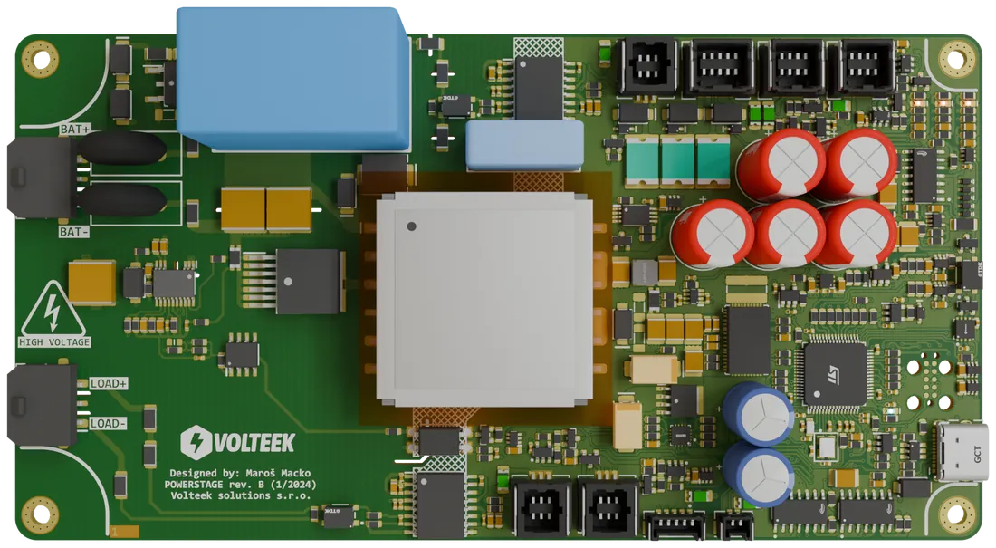
Manages the flow of energy to and from the battery. It controls the battery contactors, handles protection and measures the pack.

Parameters

HV supply
Isolated HV DC/DC converter, 100–1200 V
Insulation monitoring
Insulation Monitoring Device (IMD) support
Contactor control
12/24 V main and precharge contactors
Pack voltage accuracy
±0.1 V
Refresh rate
Up to 2 kHz

Order info

Part numberModule
BCS-PM01Power Module
Ask about BCS-PM01

Or email info@volteek.com

BCS-CM

Cell Module

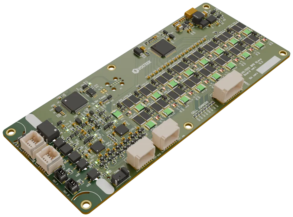
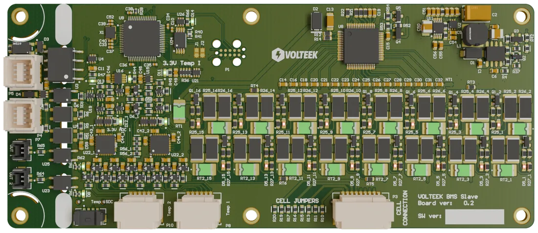
Measures and balances the cell voltages and monitors module temperatures. An intelligent balancing algorithm keeps heat generation low.

Parameters

Cells
Up to 16 HV cells
Cell voltage accuracy
Down to ±1.9 mV
Temperature accuracy
±0.1 °C
Cell voltage refresh
Down to 20 ms
Power consumption
< 50 mW
Standby power
< 160 µW
Communication
isoCAN
Safety
iSDC capability
Board outline (BCS-CM01601)
148 × 63 mm, 6 × Ø3 mm mounting holes

Order info

Part numberCellsMax. cell VBalancingTemp. inputs
BCS-CM01601165 V800 mA14
BCS-CM01201125 V800 mA14
BCS-CM0080185 V450 mA7
Ask about BCS-CM

Or email info@volteek.com

In developmentCell Module with active cell balancingActive balancing at up to 3 A on about half the footprint of BCS-CM01601, compatible with the same BCS system. See what is coming →
BCS-DM01

Display Module

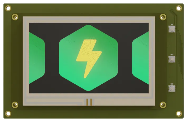
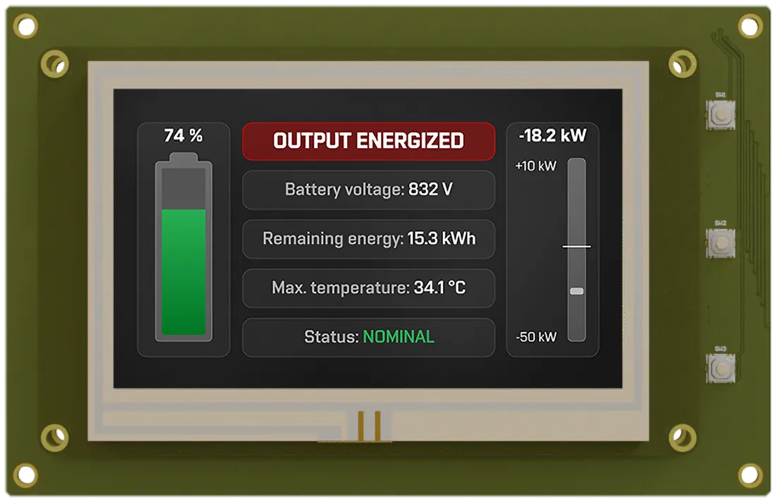
A high-contrast, high-brightness display that keeps battery status and performance readable in any conditions, so users get to the data they need quickly.

Parameters

Display
4.3″ LCD, 480 × 272
Visibility
High contrast, high brightness
Power consumption
< 2.5 W
Standby power
< 160 µW
Interface
CAN bus
Customisation
OEM customisable

Order info

Part numberModule
BCS-DM01Display Module
Ask about BCS-DM01

Or email info@volteek.com

BCS-AM01–04

Current Module

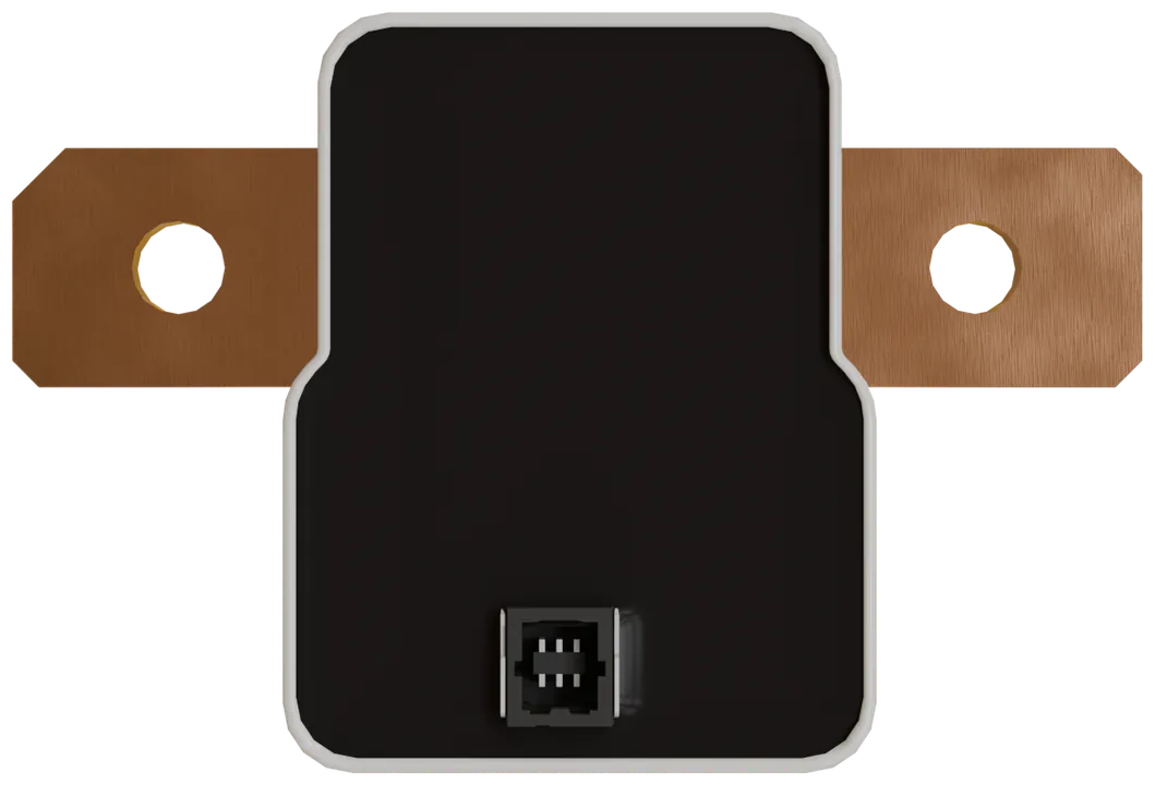
Measures the current entering and leaving the battery pack at a high refresh rate and reports to the other modules over the isoCAN bus.

Parameters

Measurement
Temperature-compensated shunt
Current ranges
±250, ±500, ±1000, ±1825 A
Current accuracy
±0.01 A
Temperature accuracy
±0.1 °C
Refresh rate
Up to 2 kHz
Communication
isoCAN
Safety
iSDC capability

Order info

Part numberMeasurement range
BCS-AM01±250 A
BCS-AM02±500 A
BCS-AM03±1000 A
BCS-AM04±1825 A
Ask about BCS-AM01–04

Or email info@volteek.com

Cell ModuleIn development

Cell Module with active cell balancing

We are developing a cell module that balances actively. It delivers the same performance as BCS-CM01601 on about half the footprint, raises the balancing current to up to 3 A, and moves charge between cells at an expected efficiency of about 96% instead of burning it as heat. It works with the same BCS system you use today.

Of the BCS-CM01601 footprint, same performance
~50%
Balancing current, up from 800 mA
3A
Expected balancing efficiency
~96%
BCS system compatibility
Same
BCS-CM01601 cell module, top view, shown as the size referenceBCS-CM01601 · 148 × 63 mm
CELL SENSEACTIVE BALANCING STAGEISOLATIONAFEMCUisoCANActive · concept wireframe · ≈50% footprint
Size draft: a concept wireframe of the active cell module over the BCS-CM01601 render, drawn at about 50% of its footprint. Illustrative only; the layout and board outline are not final.
Compared with BCS-CM01601
BCS-CM01601 (available)Active balancing (in development)
Module footprintRelative to BCS-CM01601
Balancing currentMaximum, amps
BCS-CM01601Active balancing · in development
StatusAvailableIn development
Balancing methodPassive, surplus charge bled off as heatActive, charge moved between cells
Balancing current800 mAUp to 3 A
FootprintReference, 148 × 63 mmAbout 50%, same performance
Balancing efficiencyNone, all balancing energy becomes heatAbout 96% expected, only about 4% lost
System compatibilityBCS platform, isoCANSame, works with existing BCS modules
Where the energy goes

Balancing without the heat.

A passive balancer drains the fullest cells through resistors, so every watt it removes turns into heat inside the pack. That is why passive balancing currents stay low.

4 V × 3 A = 12 WThe heat a passive balancer would have to dissipate for every cell it bleeds at 3 A from a 4 V cell.

The active cell module moves that energy to the emptier cells instead. At an expected efficiency of about 96%, only around 4% of the energy moved is lost as heat, which is what makes a balancing current of up to 3 A practical.

  • Up to 3 A balancing current to bring large or badly mismatched packs into balance faster
  • About 96% expected balancing efficiency: surplus charge is redistributed, not wasted
  • Less heat inside the battery pack
  • About half the footprint of BCS-CM01601, with the same performance
  • Same BCS system compatibility: works with the existing master, power, current and display modules

Passive balancing

Bleeds to heat
0Cell spread
0Usable charge
0Lost as heat

Active balancing

Redistributes
0Cell spread
0Usable charge
0Lost as heat

Simplified illustration: 16 cells in series, state of charge per cell, active balancing modelled at the expected conversion efficiency of about 96%. The dashed yellow line marks the emptiest cell, which sets usable pack charge.

Longer battery lifeCells stay matched, so no single cell is pushed harder than the rest.
Higher reliabilityWeak cells are supported instead of becoming the failure point.
Better efficiencyAbout 96% of the energy moved stays in the pack instead of turning into heat.
More energy densityMore of the installed capacity is usable on every cycle.
Available today

Need a cell module now?

The released BCS-CM cell module covers 8, 12 or 16 cells per module, with ±1.9 mV cell voltage accuracy.

R&D

Capabilities beyond battery control.

Turnkey engineering solutions

Our team combines design and engineering to deliver customised solutions quickly and reliably. From concept to execution, we turn your idea into a working product with end-to-end services.

6weeks

From consultation to a finished product in as little as six weeks.

  • Transparent project tracking throughout the entire development
  • System-level design, from concept to a functional product
  • Complete project documentation and test reports
We are experts in

Software, hardware and the system around them.

Software development

From firmware to networking

From firmware for embedded systems, through user interface development, all the way to cybersecurity and networking.

Hardware design

High-speed, high-power PCBs

Design of complex high-speed and high-power PCBs, including their mechanical properties, mounting, vibration isolation and cooling.

System engineering

Architecture that fits

From system-level architecture and feasibility studies to integration into existing systems, ensuring compatibility with your current infrastructure.

We have experience with

High voltage and harsh conditions.

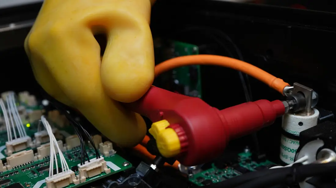
High-voltage connector being fitted with insulated gloves
High voltage

More power, less loss

We have extensive experience developing high-voltage electronics. High voltage lets us build more power-dense and efficient systems for applications where it matters.

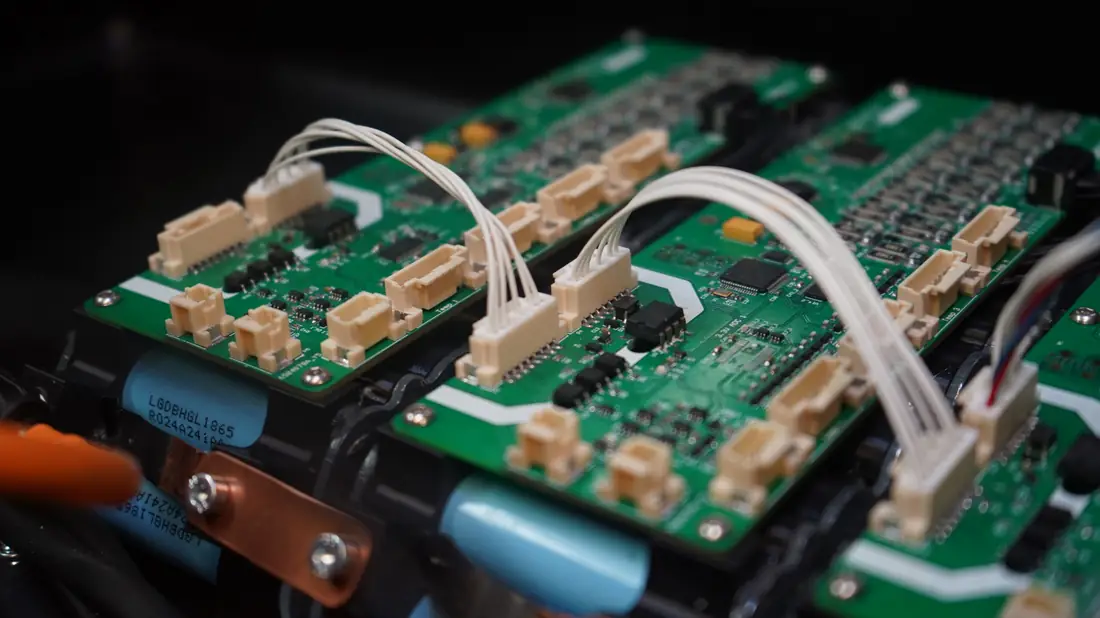
Volteek cell modules wired on a battery pack
Extreme environments

Built for heat, humidity and vibration

We have developed systems for devices that operate in extreme conditions. We design electronics and mechanical subsystems that survive a race weekend or prolonged operation in space.

Interested in working with us?

Tell us what you are building and when you need it.

Send us a message
Space tech

Per aspera ad astra.

Space grade technologies

Volteek is developing advanced battery control solutions for aerospace, space and other high-reliability applications. Our electronics already have flight heritage in orbit.

Flight heritage

Our technology is already in orbit.

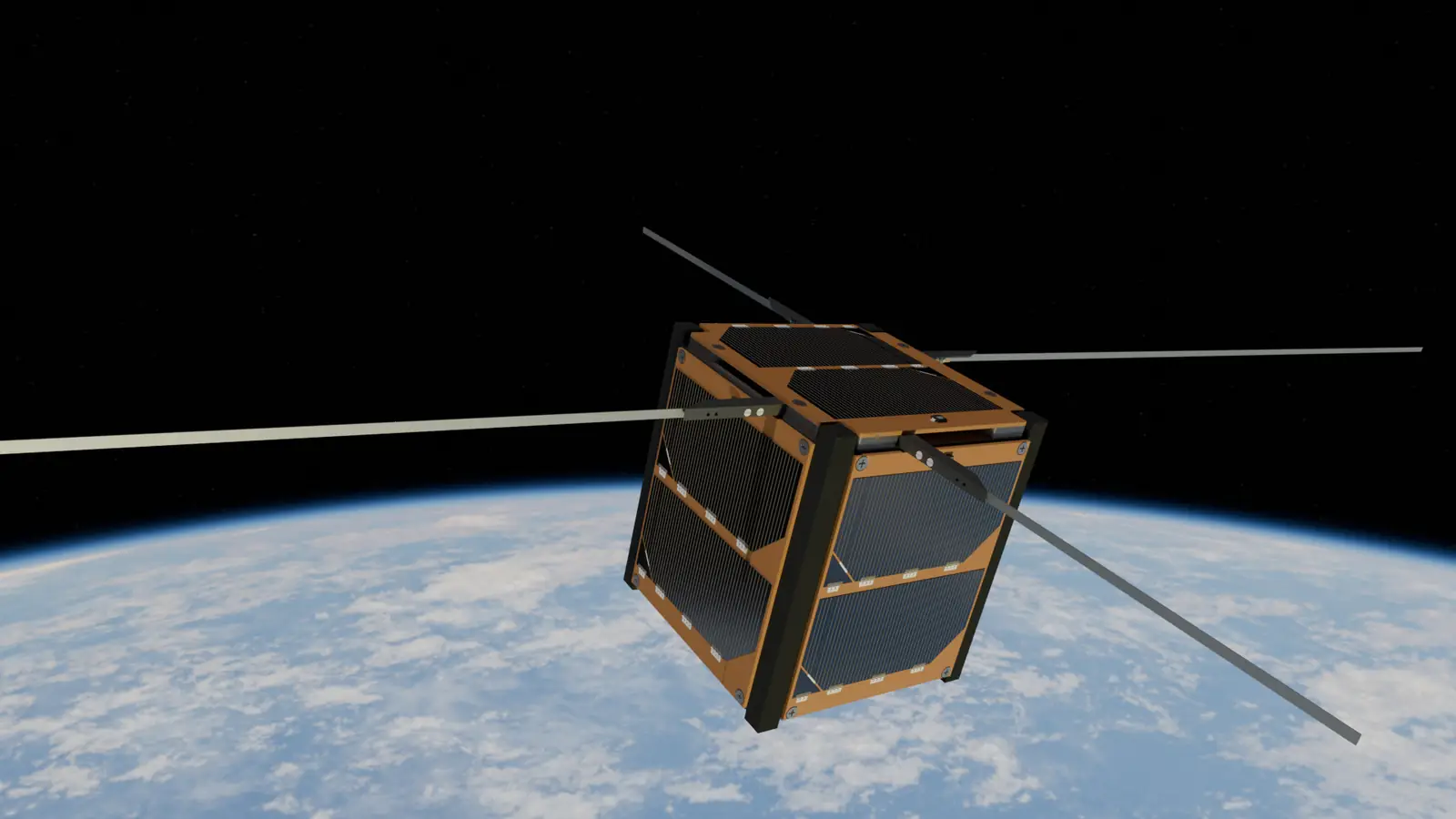
We developed the on-board computer hardware for KOSTKA, the 1U CubeSat built by the YSpace team at Brno University of Technology: a dual-processor PC/104 board with redundant memory, inertial sensing, temperature channels and a camera interface. It has been flying since July 2026.

Mission KOSTKA at cubesat.cz
KOSTKAIn orbit
Volteek role
On-board computer hardware (OBC)
Satellite
1U CubeSat, the first Czech satellite designed and built by students
Operator
YSpace, Brno University of Technology
Launch
7 July 2026, SpaceX Falcon 9, Transporter-17
Orbit
~600 km sun-synchronous, ~95 min period
KOSTKA on-board computer hardware

What we put in orbit.

A PC/104 on-board computer board for CubeSat-class missions. Our hardware combines a high-performance main processor and a lower-power coprocessor with redundant non-volatile memory, external PSRAM, spacecraft bus transceivers, inertial sensing, a parallel camera interface and four RTD measurement channels.

Stackable CubeSat format
PC/104
Main processor + coprocessor
M7+ M33
Module mass
98.7g
Operating temperature
−30…80°C
Main processor
STM32H723, Arm Cortex-M7High-performance main processing domain
Coprocessor
STM32U575, Arm Cortex-M33Lower-power secondary domain that drives the RTD converter
Non-volatile memory
3 × 128 Mbit NOR flash, 48 MiB totalPlus 3 × 4 Mbit FRAM, 1.5 MiB total, redundant devices
Working memory
8 MiB external PSRAMOn a quad-SPI interface
Reliability
External watchdog on each processorHardware watchdogs wired to each processor’s reset input
Spacecraft bus
I²C, RS-485 and CAN interfaces3.3 V logic, two 52-pin PC/104 stack connectors
Inertial sensing
MTi-3 AHRS module
Temperature
4 × two-wire PT1000 channels (LTC2984)Plus internal and on-board temperature sensors
Camera
8-bit DCMI parallel interfaceWith I²C and SPI control and a switched, protected 3.3 V camera rail
Mechanical
PC/104, about 90 × 96 mm4 × M3 mounting holes, max. 13 mm assembly thickness, single-point chassis ground
Space Battery SystemIn development

A modular battery for micro and mini satellites.

The Volteek Space Battery System is a modular, Li-ion based power storage unit for satellites from 10 to 1000 kg. Modules connect in series or parallel to scale the voltage and capacity of the battery stack.

Satellite class
10–1000kg
Cell chemistry
Li-ion
Series or parallel stacking
Modular
Redundant isolated bus
2×CAN

Scalable stack

Connect modules in series or parallel to reach the voltage and capacity the mission needs.

Flexible integration

Separate charge and discharge interfaces fit into distributed power storage architectures.

Configurable protection

Overvoltage, undervoltage, short-circuit and over-temperature protection, configurable remotely.

Autonomous management

Cell charging, active cell balancing and heating are managed on board, autonomously.

Fault management

Survival mode, watchdog recovery, safe-state transitions and startup arbitration.

Redundant telemetry

Every event is reported to the spacecraft over a redundant, isolated CAN bus.

Built to space standards

How we develop the Space Battery System, from the first requirement to flight hardware.

  • ECSSStandards complianceDeveloped in compliance with ECSS standards.
  • ESCCQualified componentsUse of ESCC-qualified components.
  • SYSTEMSystem-level designFrom concept to a functional product.
Support

Technology Incubation programme

This project is implemented with financial support from the Technology Incubation programme.

ESA Business Incubation Centre Czech Republic Czech Republic, The Country For The Future Technology Incubation, CzechInvest

Building for orbit?

Talk to us about high-reliability battery control for your mission.

Contact the team
Contact us

We’ll circle back to you.

Tailored engineering expertise

Whether you are interested in our battery control solutions or our R&D capabilities, we are here to help. Let’s shape the future together.

Emailinfo@volteek.com
Phone+420 602 649 390
Company details
Volteek solutions s.r.o.
Ječná 29a
621 00 Brno
Czech Republic
Registration

IČ: 19638515
DIČ: CZ19638515
Spisová značka: C 135473
Krajský soud v Brně